Figure Set 1. Detector Positions
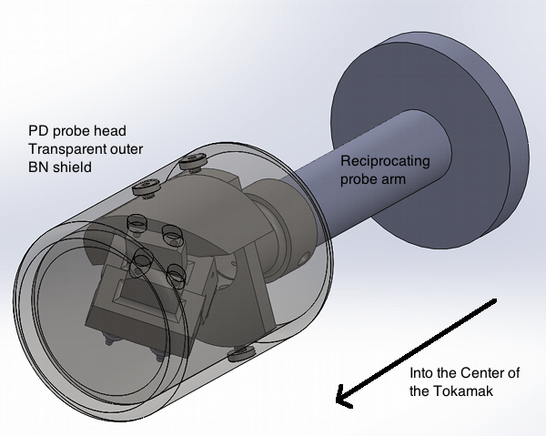
A. Note that the original image is courtesy of the CCFE Drawing Office. Channel 0 contains Detector 4, Channel 1 contains Detector 1, Channel 2 contains Detector 2, and Channel 3 contains Detector 3. The entrance of the collimators leading to each detector is visible in the image.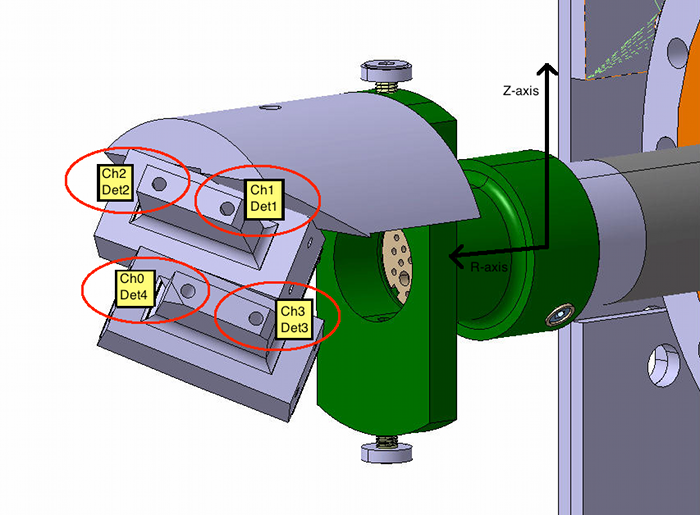 B. An image of the probe head with a transparent outer Boron Nitride (BN) shield. Note that the reciprocating probe arm's inner tube length is not drawn to scale.
 Back to Data Log
 Topic revision: r2 - 2014-06-18 - lc_2eramona

Ideas, requests, problems regarding TWiki? Send feedback
Note: Please contribute updates to this topic on TWiki.org at TWiki:TWiki.DetectorPositions.